Looks like you're enjoying the discussion, but you're not signed up for an account. When you create an account, we remember exactly what you've read, so you always come right back where you left off. You also get notifications, here and via email, whenever new posts are made. You can like posts to share the love.
  Join
Join 


You pull the plug from the mains, remove the 20\24 pin lead and plug it into the tester, plug the power back in and it will automatically run, in this case the LED's are a simple traffic light system that reports good or bad for each of the various leads it has.
This one also has ports to use a proper electrical meter as well, nit sure if that required by the newer ones around that give a digital read out instead of this LED method, price ranges a fair bit, but I guess something around $20 or so is an average price for you, but when finished just unplug the mains again, replace the lead(s) and your back to where you started, very useful safe way to check a PSU as it require no special training, just use it as described here and it does the rest.
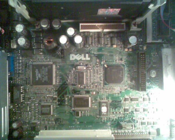
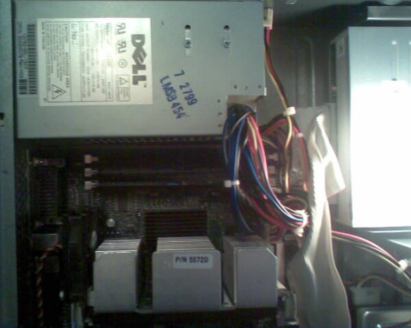
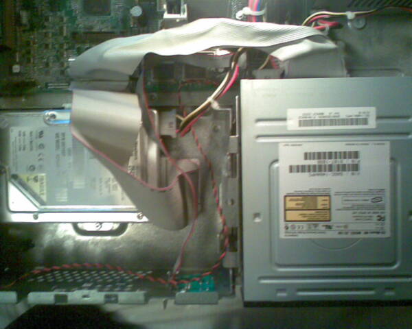
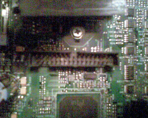
But are you able to take some more pic's of the inside, so to cover ALL the various connections so we can double check there is nothing out of place, but if you could add some lighting to the case so the pic's are clear it would be a great help, maybe you have an adjustable light or can use a table lamp maybe to add more light, that would be a great help.